Thursday, November 3, 2016

Home Assistant

Wanting to expand my home automation setup, it was time to find a unifying infrastructure to tie it all together. The open source community project Home Assistant is a great tool for just that. However it can be a lot of frustrating work, as things can easily go wrong and the amount of forum posts is somewhat pitiful. This is my attempt to document some of my experience in order to save some time during my next installation.

My first piece of advice is to use the raspberry pi all in one installer. Only after spending about 10 hours trying to get it setup for my regular linux server did i finally give in and switch. About 2 hours  later (most of which was simply waiting for the installer) I had working installation on my rapsberry pi 2 with all the right permissions and virtual environments. It even had open z-wave control panel ready to start, which I would definitely be using.

Open z-wave control panel (ozwcp), was by far the most difficult part to get running correctly and then use. The good news however is that once you know how it works and what it's for, it's quite easy to reuse. Indeed i just added a new light switch to home assistant using ozwcp in under 5 minutes.
The purpose of ozwcp is simply to provide a gui for writing the z wave configuration xml file that home assistant uses later. These are the steps i have found to be most simple and effective.

Step 0: I find it's easiest to "include" my new z wave module into my z wave setup by doing this outside of ozwcp. Using the Aeon Labs Aeotec Z-Wave Z-Stick, Gen5 (ZW090) simply unplug the transmitter from your box and get in range of the new device. Press once to enable pairing mode, then pair with new device. Hopefully your device comes with instructions on how to include it in a zwave network. If successful, plug your transmitter back into the hass box and continue to step 1. If not, your new device probably doesn't have power/see other troubleshooting advice.

Step 1: Stop Home Assistant, either through the web app rest calls, or by killing the service on the box it's running on. If you can no longer hit the web page and instead see a 503, this should be enough.

Step 2: Start the ozwcp executable. In order to do this you'll need to ssh into your box running hass and cd to the directory where the ozwcp executable file exists. For me that is

cd /srv/hass/src/open-zwave-control-panel/

then run the executable on some port

./ozwcp -p 8888


Step 3: Point your browser to ozwcp 192.168.1.{hassBox}:8888

Step 4: Initialize your z wave transmitter device by looking up it's tty listing or by entering the id. There are plenty of instructions on how to do this, so i'll just skip to showing you what mine looks like.

/dev/serial/by-id/usb-0658_0200-if00

Theoretically this reference by id should never change and thus should always work. But sometimes i've found that it does not. In those instances, i tried looking up the tty listing (ls /dev/ttyACM*) and using that entry which then works. Remember not to check the usb button even though clearly mine says usb in the id.

Step 5: This is the confusing part because no one ever explains that after initializing you should see your z wave transmitter and any other device that's already included in the network. Granted, it's only confusing when it doesn't work, cause you are given no helpful directions as to what you should do next.

 
If nothing appears, something has already gone wrong and there is no point in playing with the buttons to try and make things appear. Some possible reasons are that your transmitter is not plugged in or needs to be reinserted. Make sure it shows up in the ttyACM* list. You could also try digging through the error logs, but the errors codes are completely cryptic and usually unhelpful.

As I said, when it works, it's pretty easy. All you have to do now is customize your devices. Use the functions drop down to set a name or location. Also note customizing is optional, but you should definitely be seeing your devices before moving on.

Step 6: This step is not optional and very important. Make sure you press save under the Backup Controller menu. This is what actually writes your devices to the z wave xml that home assistant looks up.

Step 7: Close ozwcp and start hass
sudo systemctl start home-assistant.service

Step 8: If discovery is off, add a configuration entry and name it however you want.

sudo nano /home/hass/.homeassistant/configuration.yaml

Once it boots up and you can see the web page, look under the dev-state page to see your device. You'll need to use the Entity name when referencing this device in your hass config. Usually it's something like light.__level_4_0 or switch.vision_zl7432_inwall_switch_dual_relay_switch_3_0

Here's an example configuration entry.

customize:
    switch.vision_zl7432_inwall_switch_dual_relay_switch_3_0_2:
      friendly_name: 'Master Lights'
      icon: mdi:lightbulb


Fortunately there are plenty of examples and the documentation is pretty well covered on what things mean.


That's it!


Friday, February 19, 2016

Are you still opening your garage door with a button?


This project's goal was to be able to automate my garage door so that instead of only being able to use the wall button or a car remote, I can send a signal from anywhere and the door will open or close. 


When I told people my idea to automate my garage door, many people felt it was not a problem that needed to be solved. And they're right. But when home automation is your hobby, eventually you run out of necessary things to automate. It turned out to be a lot of work -- a lot more than pushing the button ever was. But having had it setup for a couple weeks now. It's pretty fun to use and so nice to be able to drive right into the garage without waiting that extra 5 seconds.

Waiting 5 seconds for your door to go up an average of just two times a day, adds up to 1 hour of waiting each year!


Automating my garage door has easily been the most elaborate project I've ever worked on. That's because, the only easy solution is to buy a smart garage door opener which cost about $600+. My solution cost me about $15 because I had most of the equipment already including

  • a raspberry pi
  • wifi adapter
  • sd card
  • pi enclosure
  • power supply (usb micro cord and wall adapter)
The equipment I had to buy was


Starting from scratch with none of these materials might set you back about $80. But my solution was created specifically because I had most of the equipment already. That, and now I finally have a "sweet" use for my Raspberry Pi.


Figuring out the hardware was tricky for me because I don't have much experience in small electronics. Nevertheless, there are basically four main elements to this solution.

  1. Configure the raspberry Pi to act as a REST server and forward signals to the pins
  2. Wire up the pin signal to trigger the opening and closing on the motor. 
  3. Add a sensor to detect the current position of the door. Without this, you cannot build reliable application logic.
  4. Expose the server endpoints and write an app that can trigger them either through some UI buttons or a geofence, or both.


Finished Product

Part 1

Configure the raspberry Pi to be a server

I did some investigation and found a wonderful library called Webiopi that did exactly what I needed. With just a few lines in the terminal you can setup a server just for REST calls or to host an html site. Since all I needed was REST, I left most of the configuration file to its default settings and just specified a python app to load. This framework was perfect for two reasons:

  • To expose the methods for my rest layer,  I simply annotated the methods with @webiopi.macro
  •  It had built-in classes to configure and send signals to the GPIO board.

Here's the python app I load into the service at launch.


 1
 2
 3
 4
 5
 6
 7
 8
 9
10
11
12
13
14
15
16
17
18
19
20
21
22
23
24
25
26
27
28
29
30
31
32
33
34
35
36
37
38
39
40
41
42
43
44
45
46
47
48
49
50
51
52
53
54
55
56
57
import webiopi
import datetime
from webiopi.utils import types

GPIO = webiopi.GPIO
LIGHT = 23
SENSOR = 27
 
def setup():
 GPIO.setFunction(LIGHT, GPIO.OUT)
 GPIO.setFunction(SENSOR, GPIO.IN, GPIO.PUD_DOWN)

def loop():
 webiopi.sleep(3)

def destroy():
 GPIO.digitalWrite(LIGHT, GPIO.LOW)

def activate():
 GPIO.digitalWrite(LIGHT, GPIO.HIGH)
 webiopi.sleep(2)
 GPIO.digitalWrite(LIGHT, GPIO.LOW)

def isOpen():
 open = GPIO.digitalRead(SENSOR)
 print("Current state is:")
 if open is True:
  print("OPEN")
 else:
  print("CLOSED")
#returns true if voltage is high
 return open

@webiopi.macro
def getState():
 json = {}
 if isOpen() is False:
  json['closed'] = True
 else:
  json['closed'] = False
 return types.jsonDumps(json)

@webiopi.macro
def openDoor():
 if isOpen() is False:
  print("OPENING")
  #json = getState()
  activate()
 return types.jsonDumps({"action":"Opening"})

@webiopi.macro
def closeDoor():
 if isOpen() is True:
  print("CLOSING")
  #json = getState()
  activate()
 return types.jsonDumps({"action":"Closing"})
Using the @webiopi.macro annotation, I have exposed 3 methods, openDoor(), closeDoor() and getState(). Being able to receive input on the SENSOR variable allows my code to do more than execute activate() as I leave the house and hope that the signal was sent without errors.

By having this state information I can confidently send a closeDoor() command without worrying that I'm actually opening an already closed door. You'll also notice the setup(), loop() and destroy() methods. These are part of the webiopi framework and you can override them with any custom logic. In my case I simply needed to initialize the pins I would be using later for input and output. Later on, I'll talk about why that third argument (GPIO.PUD_DOWN) is necessary.

To finish off part 1, I had to figure out how to call these methods via rest. Here's how you would hit the getState() method.

POST /macros/getState HTTP/1.1
Host: 192.168.1.17:8000
Authorization: Basic {{username:password}}

As you can see, the path for rest endpoints simply starts at /macros/ and you must include your Authorization header with the base64 encoded username and password (default is webiopi:raspberry). If you want to hit this from outside your home network, you'll need a domain or static IP and port forward 8000 to hit your raspberry pi. Also make sure you use POST, instead of GET (even though it should be a GET). Perhaps there is a more appropriate annotation, but I don't care.


Part 2

Signals from pins activate the motor

This part is actually pretty simple once you have the right equipment. In the code above, pin 23 (variable name LIGHT) was activated anytime the door needed to change. If you don't know anything about relays, they are essentially a way to turn a small electrical signal into a stronger one. In this case, the Raspberry Pi has a 3.3v output pin and the garage door opener might need something stronger than that (though I actually never tested it going direct, which is why I mentioned earlier, that you might not need the relay). Here's a diagram labeling how the pins were connected to the relay. Ground and 3.3v were arbitrary/whatever was available.

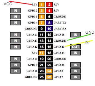
The GPIO board of the PI with pins connecting to the relay


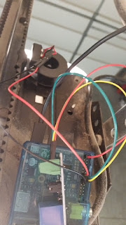
The relay then connects from the NO and COM directly into the same ports as the wall button wires. This makes the solution especially convenient when it's time to move. Simply remove the wires and nothing has changed. Also, with this configuration, I can still use all the same remotes and buttons that currently exist on the system.


The Green wires come from the relay and fit right alongside the wires from the wall button. No splicing required.


Part 3

Detect current position of door

This part took a while to get right. Not because the solution is complicated, but because I didn't understand it very well. To read the state of the door, I used a magnetic switch. When the magnets line up, the signal can flow. So you create a circuit from the board, through the switch, then back to the board. Connect a 3.3v pin to the COM on the switch, then from NC on the switch back to the input pin that you've registered in your program. From my code you can see I setup pin 27 (variable named SENSOR) as my input during the setup loop. NC stands for Normally Closed, because our door will normally be closed. Though technically you could use NO, if you reversed your application logic.

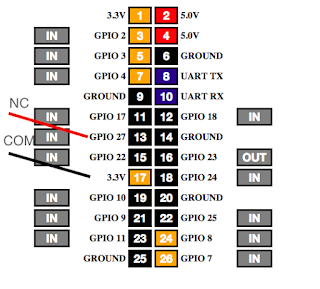
GPIO Board showing connections to magnetic switch


When I got to this point I started testing the input signal. Using the GPIO dashboard that comes with webiopi, I noticed that the input pin would constantly flip between on and off regardless of whether the magnet was aligned. To solve this problem I had to be educated about pull down resistors.

<Pull Down Resistor Explanation>

The third argument (GPIO.PUD_DOWN) is necessary because the signal that will flow through this small circuit is analog. An analog signal doesn't produce a 0, it produces a current slightly less than the 3.3v. But since the pi is expecting a digital signal of 0, it switches back and forth between on and off. A pull down resistor is an actual piece of hardware that just acts like a buffer for all the low voltages. Until the buffer fills, by receiving a high signal, the resistor will pass on a 0. Luckily the PI has this resistor capability built in and it simply needs to be configured to use it, hence the third argument.

</Pull Down Resistor Explanation>

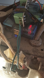
Once I could safely rely on the signal, I placed the magnets. The rubber track/chain ended up being the easiest place to mount a magnet that wouldn't fall and that would line up with my receiver.
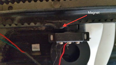
The magnet switch
When aligned, the current can flow. A "high" signal tells us that the state of the door is closed.


The stationary portion of the magnet switch connects to the pi and lines up directly with an ordinary magnet (taped to the rubber track) only when the door is fully closed. I recommend establishing the "lined up" state to a closed door instead of open, as this will greatly reduce your risk of a false positives.

Part 4

The mobile app. Lest what's all this been for?

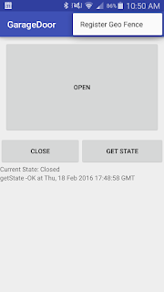
Finally I was back in my comfort zone. A simple UI with a few buttons (like Open, Close and Get State) was enough to put a smile on my face.


But I also wanted to have it be fully automated. As soon as I would get within a block or so of my house, the garage would just open. For this to happen, I needed to create a geofence.


Geofences work like this on Android:

  • You setup a circular virtual fence around a center coordinate. 
  • You tell it that you want to watch for an entry, exit, or dwell event (or all three). 
  • You attach a PendingIntent to the trigger of any of these events. 
  • You submit this to the Android geofence directory. 
  • The system then takes care of launching your pending intent when any of the events you registered for happen. 
  • During the execution of your pending intent, you can see which type of event was the trigger and from there determine the appropriate logic. For example, on an entry event, I would want to call the open function, and for an exit event, the close function. 


A couple things to note:

  • The GPS sensor must be active in order to realize it's inside a geofence. This has resulted in me opening the maps app as I pull in to the last stretch of my drive home so that it's constantly refreshing. So much for being fully automated. 
  • When you submit your geofence to the Android geofence directory, it will immediately fire off your pending intent if any of the events are active. In other words, if you are inside your geofence while submitting, it will fire off an entry event. This was the reason I stopped registering the geofence on app launch. Because while coding at home, with each restart of the app, my garage door would open. 
  • Lastly, from what I've read, the OS clears the list of registered Geofences with each restart. So instead of registering the same geofence with each app launch, it's inside a menu option which I will have to periodically press whenever I restart my phone. 
  • The execution of the pending intent will be completely unnoticeable unless you display something. For myself, I decided to show a notification indicating which method was fired, or if there was a failure.
The code is hosted on btibucket.

If you have any questions, please leave a comment and I will definitely respond.

Friday, November 20, 2015

Comskip: For my next trick, I'm going to make these commercials dissapear

For a couple months now I've been recording live tv as in comes in through my Over the air antenna with the help of my TabloTV. Check out this blog post to see how I copy the recorded shows from the tablo to my plex server.

But the idea came to me to take it a step further. Although it's nice that I can record these shows and watch them at my leisure (and even fast forward through any parts i want to) it's still pretty annoying to have to fast forward through the commercials.


As I searched around for a tool to fix this, I found several programs such as Avidemux that allow you to remove commercials (or any part) with relative ease and speed. I'm still not sure if Avidemux is a play on Avid (the sophisticated editing software) or A vide'o mux'er. Either way, there was one problem with these tools -- they were GUI based, which meant that automation would be difficult if not impossible.


Finally I found a tool that could also be used in the terminal -- Comskip. Comskip uses cues in the video such as black frames, audio silence/changes, and more to detect when commercials start. Then it outputs an ".edl" file which stands for edit decision list. The linux version isn't as well distributed as the windows version so I had to compile it from source and download some dependencies.
This page is where i started.

It requires ffmpeg 0.9 or greater and argtable2.

cd /var/tmp
mkdir ComSkipWork
wget http://ffmpeg.org/releases/ffmpeg-2.2.tar.bz2
tar xf ffmpeg-2.2.tar.bz2
cd ffmpeg-2.2
./configure --prefix=/var/tmp/ComSkipWork/install
make -j8
make install
cd ..
wget http://www.xilka.com/xilka/source/comskip-0.93i.tar.xz
tar xf comskip-0.93i.tar.xz
cd comskip-0.93i
PKG_CONFIG_PATH=/var/tmp/ComSkipWork/install/lib/pkgconfig ./configure --prefix=/usr
make -j8
sudo make install


Following the above steps line for line worked perfectly except for one spot


Running make -j8 shows an error about yasm not being installed. Simply run
sudo apt-get install yasm
**If you have other problems see the bottom of this post. I actually didn't start with the above steps and therefore ended up installing a lot things on my own which may or may not be necessary.**

Now that I had comskip installed, it was time to create/setup an .ini file.
A quick google search also revealed that some have customized their .ini files for different regions.

I downloaded USA_General by Wilky13.

For my purposes I just needed to make sure that it would produce an .edl file. After confirming it that, I could now run:
comskip "filename"
and get an .edl file which tells where the commercials are.


So using the .edl file I wrote a python script to scan for any raw videos (which in my case are always .mp4 files) and compress them into .mkv files. From there it analyzes the mkv file and creates multiple temp files of the content between commercial breaks -- or the actual show. The script then concatenates these temp files into a new mkv and moves the compressed version to a backup folder in case there was a mistake. Then it cleans up all the temp files and scans for the next raw mp4. Running from a cron job every night, the OTA shows goes all the way from being recorded to the tablo, copied to my hard drive, compressed and spliced, then loaded into plex automatically.

The code is a little sloppy, but one needs to simply modify the constants including path to a static ffmpeg, and the root directory of where all their tv shows are kept.
For example, on my server


I simply point to /../TabloTv/tv and all folders and sub folders in tv will be scanned.

Here's the python script.

usage:
./removeCommercials.py
(scans all folders and subfolders found in constants.TV_FOLDER)

or

./removeCommercials.py /path/to/filename
(executes script against passed in video only)

removeCommercials.zip


#cordCutter


TROUBLESHOOTING

My first attempt followed these similar steps (i already had a static build of ffmpeg so i thought i wouldn't need it here--wrong!!), but ended with much different results.

cd /var/tmp
mkdir ComSkipWork
wget http://www.xilka.com/xilka/source/comskip-0.93i.tar.xz
tar xf comskip-0.93i.tar.xz
cd comskip-0.93i
./configure --prefix=/usr
make -j8
sudo make install

Right about here
./configure --prefix=/usr
you might hit a error like this:
configure: error: *** A compiler with support for C++11 language features is required.
Ubuntu comes with the g++ compiler, but doesn't seem to cut it. Go ahead and run
sudo apt-get install g++
Now you might hit this issue:
 No package 'libavcodec' found
Another simple fix
 sudo apt-get install libavcodec-dev
And while you're at it
 sudo apt-get install libavformat-dev
 sudo apt-get install libargtable2-dev 


Friday, October 9, 2015

Open Sprinkler

As summer approached this year I realized my sprinkler controller was broken and my grass started to die. As a new homeowner, I was terrified and needed to find a new controller. Not wanting to buy a dinosaur i looked into smart controllers and found Open Sprinkler. There are other smart sprinkler systems but this one is by far the cheapest and from what i could tell, there are no real disadvantages.

As the name indicates it is an open source project and thus there is probably more assembly required than with a branded commercial product. But when it came down to it, installation was very easy. I simply switched the wires from the old controller


to the different zones on the new controller.


I was also able to reuse the power cord from my old controller and do all this setup in less than 20 minutes.

The real problem then came when i had to figure out a way to get my device connected to the internet. The controller has an ethernet port and wifi adapters can be purchased separately, but i had decided ahead of time i would try to convert my old raspberry pi into an adapter. After about two days following every tutorial i could and with no success i finally found an alternative solution. I used an old router (flashed with DD-WRT) to create a bridge. Now the router was working in reverse to receive internet connection over Wi-Fi and send it out through the ethernet into the Open Sprinkler controller. Within 30 minutes I had a connected open sprinkler system and was able to test all the zones.


Since that time i have not needed to use or even look at the controller sitting in the garage as all configuration can be done through either a free app or on a website which is served by the controller on your local network. Oh and did i mention that you can do remote access as well via port 80. Since I was already running a web server on port 80, I had to setup a subdomain and proxy to forward requests to the controller. It looks like this.
<VirtualHost *:80>
 ServerName sprinkler.tengentllc.com
 ProxyRequests Off
 <Proxy *>
  Order deny,allow
  Deny from all
  Allow from 192.168.1.4
 </Proxy>
 ProxyPass / http://192.168.1.4:80/
 ProxyPassReverse / http://192.168.1.4:80/
 <Location />
  Order allow,deny
  Allow from all
 </Location>
</VirtualHost>

Other great features include Weather and logs. By creating a developer account with weatherundergound.com your system can automatically access weather information and prevent recurring cycles if for example, it just rained that day. The logs are great as well and allow me to see total water usage and runtimes.

So glad I decided not to replace my broken controller with something like this!


Friday, May 8, 2015

Tablo Followup

I mentioned before that I would follow up on my post about TabloTv after I'd had some more experience with it.

The tablo tv is easy enough to setup and setting up recording is pretty straightforward too. I'm glad that I've had the 30-day trial for the TV guide feature and think i will be subscribing once it expires. Watching recorded shows via the Tablo interface or app was never my intention and i'm glad that this was the case as the startup can be a little slow at times. Upon entering the web client there is a "syncing" screen that appears and prevents you from doing anything for 30 seconds to a minute. Then when you decide on an episode to watch it can take 20 - 30 seconds before it actually starts playing. Playback is pretty smooth from that point on and I do like the live tile preview when using the 30 second and 20 second FF and RW buttons, but it's a little slow when compared to Plex which is more or less instantaneous depending on your setup. But the biggest downside is that I cannot easily share my recorded content as I have grown accustomed to in sharing my Plex library.


My intention with purchasing the Tablo was to record the shows and then allow Plex to be the player. Although there is a free Plex channel for Tablo which makes it very easy to view and play my Tablo library, I cannot share Plex channels the same way I share Plex libraries.

So I scoured the web and found this little gem. Actually it's a python script (insert ruby joke).


Essentially I've setup the Tablo to record the shows I want. This script (which runs on a cron job every night)


 pulls any newly recorded shows from the Tablo and places them into a library I've created on Plex called TabloTV. I've enabled Plex to automatically update my library twice a day so that every morning I wake up, all my new shows are there. Now I can share this TabloTV library with anyone else and goodbye HULU/Network sites, hello on-demand streamable, shareable, DVR with the freshest content available on all 4 networks.

The one downside is that I now have two copies of every episode. One of my Tablo and one on Plex. But no matter, the Tablo has a nice Auto Delete feature which I'm sure will free up space JIT style. I didn't think I would need the 4-tuner so I opted for the 2-tuner. What I didn't realize was that basically all the good shows run at the same time, so if I could do it again I would get the 4-tuner. But maybe it's a good thing. I probably watch too much TV as it is.


#Tablo
#Plex
#cordCutter

Wednesday, April 8, 2015

Tablo

"Somewhere in Las Vegas, a man just threw his Television outside his hotel room window."
            -Simon Cowell

Why do I remember this line from American Idol season 6 (which aired over 8 years ago)? Because it was hilarious. Would I ever go back and watch this season now that I know who won??? Doubtful. It's no wonder reality TV competition shows aren't on Netflix. But then what are the cord cutters who like The Bachelor and The Voice to do?!

Enter Tablo.

Basically it records OTA TV. With a plex plugin, it should be a snap to watch current shows both at home and remotely.

Since i don't actually have the device yet, (it's on the way) i'll be doing a follow up piece next week.

Wednesday, April 1, 2015

Why another timesheet app?

There are a lot of apps and websites that help you keep track of time.

For most of these the use cases vary slightly. Many are for an independent contractor wanting to keep track of their time so that they can properly charge their clients when the job has finished. Some are more of a employee manager relationship which is where mine fits in.

One of the apps I've seen is called FotoPunch. FotoPunch looks very professional and well developed. It also costs a lot. Timesheet by TengenT LLC is catered to the average small business owner. The point is to save money and find a happy medium between manual labor to enter the information and an automated system that doesn't cost a lot.

Timesheet focuses on the most important features.

1) Manage time accurately.

  • Employees use the simple UI and can the system takes care of recording precision.


2) Data in usable format

  • The app makes it easy to export a timesheet between any date range. It auto calculates and summarizes the most important information.


3) Built in safeguards

  • The system automatically checks for inconsistencies and flags these behaviors. For example, if the employee should clock in and out in the same place, the shift will be flagged if this does not happen.

4) Cost effective
  • As mentioned above, the focus is to make this a more cost effective option. So it will be priced below other alternatives.
Who would benefit from this app? What features would you want to see?