This project's goal was to be able to automate my garage door so that instead of only being able to use the wall button or a car remote, I can send a signal from anywhere and the door will open or close.
When I told people my idea to automate my garage door, many people felt it was not a problem that needed to be solved. And they're right. But when home automation is your hobby, eventually you run out of necessary things to automate. It turned out to be a lot of work -- a lot more than pushing the button ever was. But having had it setup for a couple weeks now. It's pretty fun to use and so nice to be able to drive right into the garage without waiting that extra 5 seconds.
 | |
|
Automating my garage door has easily been the most elaborate project I've ever worked on. That's because, the only easy solution is to buy a smart garage door opener which cost about $600+. My solution cost me about $15 because I had most of the equipment already including
- a raspberry pi
- wifi adapter
- sd card
- pi enclosure
- power supply (usb micro cord and wall adapter)
- a magnetic switch
- a relay (This might not actually be necessary)
- some jumper wires
Starting from scratch with none of these materials might set you back about $80. But my solution was created specifically because I had most of the equipment already. That, and now I finally have a "sweet" use for my Raspberry Pi.
Figuring out the hardware was tricky for me because I don't have much experience in small electronics. Nevertheless, there are basically four main elements to this solution.
- Configure the raspberry Pi to act as a REST server and forward signals to the pins
- Wire up the pin signal to trigger the opening and closing on the motor.
- Add a sensor to detect the current position of the door. Without this, you cannot build reliable application logic.
- Expose the server endpoints and write an app that can trigger them either through some UI buttons or a geofence, or both.
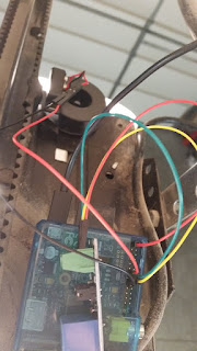 |
| Finished Product |
Part 1
Configure the raspberry Pi to be a server
I did some investigation and found a wonderful library called Webiopi that did exactly what I needed. With just a few lines in the terminal you can setup a server just for REST calls or to host an html site. Since all I needed was REST, I left most of the configuration file to its default settings and just specified a python app to load. This framework was perfect for two reasons:- To expose the methods for my rest layer, I simply annotated the methods with @webiopi.macro
- It had built-in classes to configure and send signals to the GPIO board.
Here's the python app I load into the service at launch.
1 2 3 4 5 6 7 8 9 10 11 12 13 14 15 16 17 18 19 20 21 22 23 24 25 26 27 28 29 30 31 32 33 34 35 36 37 38 39 40 41 42 43 44 45 46 47 48 49 50 51 52 53 54 55 56 57 | import webiopi import datetime from webiopi.utils import types GPIO = webiopi.GPIO LIGHT = 23 SENSOR = 27 def setup(): GPIO.setFunction(LIGHT, GPIO.OUT) GPIO.setFunction(SENSOR, GPIO.IN, GPIO.PUD_DOWN) def loop(): webiopi.sleep(3) def destroy(): GPIO.digitalWrite(LIGHT, GPIO.LOW) def activate(): GPIO.digitalWrite(LIGHT, GPIO.HIGH) webiopi.sleep(2) GPIO.digitalWrite(LIGHT, GPIO.LOW) def isOpen(): open = GPIO.digitalRead(SENSOR) print("Current state is:") if open is True: print("OPEN") else: print("CLOSED") #returns true if voltage is high return open @webiopi.macro def getState(): json = {} if isOpen() is False: json['closed'] = True else: json['closed'] = False return types.jsonDumps(json) @webiopi.macro def openDoor(): if isOpen() is False: print("OPENING") #json = getState() activate() return types.jsonDumps({"action":"Opening"}) @webiopi.macro def closeDoor(): if isOpen() is True: print("CLOSING") #json = getState() activate() return types.jsonDumps({"action":"Closing"}) |
By having this state information I can confidently send a closeDoor() command without worrying that I'm actually opening an already closed door. You'll also notice the setup(), loop() and destroy() methods. These are part of the webiopi framework and you can override them with any custom logic. In my case I simply needed to initialize the pins I would be using later for input and output. Later on, I'll talk about why that third argument (GPIO.PUD_DOWN) is necessary.
To finish off part 1, I had to figure out how to call these methods via rest. Here's how you would hit the getState() method.
POST /macros/getState HTTP/1.1
Host: 192.168.1.17:8000
Authorization: Basic {{username:password}}
As you can see, the path for rest endpoints simply starts at /macros/ and you must include your Authorization header with the base64 encoded username and password (default is webiopi:raspberry). If you want to hit this from outside your home network, you'll need a domain or static IP and port forward 8000 to hit your raspberry pi. Also make sure you use POST, instead of GET (even though it should be a GET). Perhaps there is a more appropriate annotation, but I don't care.
Part 2
Signals from pins activate the motor
This part is actually pretty simple once you have the right equipment. In the code above, pin 23 (variable name LIGHT) was activated anytime the door needed to change. If you don't know anything about relays, they are essentially a way to turn a small electrical signal into a stronger one. In this case, the Raspberry Pi has a 3.3v output pin and the garage door opener might need something stronger than that (though I actually never tested it going direct, which is why I mentioned earlier, that you might not need the relay). Here's a diagram labeling how the pins were connected to the relay. Ground and 3.3v were arbitrary/whatever was available.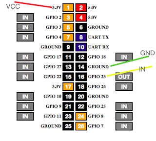 | |
|
The relay then connects from the NO and COM directly into the same ports as the wall button wires. This makes the solution especially convenient when it's time to move. Simply remove the wires and nothing has changed. Also, with this configuration, I can still use all the same remotes and buttons that currently exist on the system.
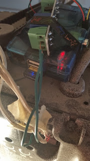  |
| The Green wires come from the relay and fit right alongside the wires from the wall button. No splicing required. |
Part 3
Detect current position of door
This part took a while to get right. Not because the solution is complicated, but because I didn't understand it very well. To read the state of the door, I used a magnetic switch. When the magnets line up, the signal can flow. So you create a circuit from the board, through the switch, then back to the board. Connect a 3.3v pin to the COM on the switch, then from NC on the switch back to the input pin that you've registered in your program. From my code you can see I setup pin 27 (variable named SENSOR) as my input during the setup loop. NC stands for Normally Closed, because our door will normally be closed. Though technically you could use NO, if you reversed your application logic.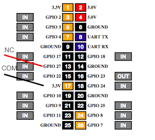 |
| GPIO Board showing connections to magnetic switch |
When I got to this point I started testing the input signal. Using the GPIO dashboard that comes with webiopi, I noticed that the input pin would constantly flip between on and off regardless of whether the magnet was aligned. To solve this problem I had to be educated about pull down resistors.
<Pull Down Resistor Explanation>
The third argument (GPIO.PUD_DOWN) is necessary because the signal that will flow through this small circuit is analog. An analog signal doesn't produce a 0, it produces a current slightly less than the 3.3v. But since the pi is expecting a digital signal of 0, it switches back and forth between on and off. A pull down resistor is an actual piece of hardware that just acts like a buffer for all the low voltages. Until the buffer fills, by receiving a high signal, the resistor will pass on a 0. Luckily the PI has this resistor capability built in and it simply needs to be configured to use it, hence the third argument.
</Pull Down Resistor Explanation>
Once I could safely rely on the signal, I placed the magnets. The rubber track/chain ended up being the easiest place to mount a magnet that wouldn't fall and that would line up with my receiver.
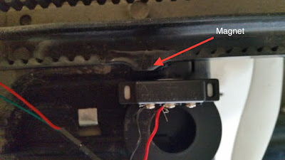 |
| The magnet switch When aligned, the current can flow. A "high" signal tells us that the state of the door is closed. |
The stationary portion of the magnet switch connects to the pi and lines up directly with an ordinary magnet (taped to the rubber track) only when the door is fully closed. I recommend establishing the "lined up" state to a closed door instead of open, as this will greatly reduce your risk of a false positives.
Part 4
The mobile app. Lest what's all this been for?
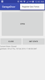 Finally I was back in my comfort zone. A simple UI with a few buttons (like Open, Close and Get State) was enough to put a smile on my face.
But I also wanted to have it be fully automated. As soon as I would get within a block or so of my house, the garage would just open. For this to happen, I needed to create a geofence.
Geofences work like this on Android:
- You setup a circular virtual fence around a center coordinate.
- You tell it that you want to watch for an entry, exit, or dwell event (or all three).
- You attach a PendingIntent to the trigger of any of these events.
- You submit this to the Android geofence directory.
- The system then takes care of launching your pending intent when any of the events you registered for happen.
- During the execution of your pending intent, you can see which type of event was the trigger and from there determine the appropriate logic. For example, on an entry event, I would want to call the open function, and for an exit event, the close function.
A couple things to note:
- The GPS sensor must be active in order to realize it's inside a geofence. This has resulted in me opening the maps app as I pull in to the last stretch of my drive home so that it's constantly refreshing. So much for being fully automated.
- When you submit your geofence to the Android geofence directory, it will immediately fire off your pending intent if any of the events are active. In other words, if you are inside your geofence while submitting, it will fire off an entry event. This was the reason I stopped registering the geofence on app launch. Because while coding at home, with each restart of the app, my garage door would open.
- Lastly, from what I've read, the OS clears the list of registered Geofences with each restart. So instead of registering the same geofence with each app launch, it's inside a menu option which I will have to periodically press whenever I restart my phone.
- The execution of the pending intent will be completely unnoticeable unless you display something. For myself, I decided to show a notification indicating which method was fired, or if there was a failure.
The code is hosted on btibucket.
If you have any questions, please leave a comment and I will definitely respond.
If you have any questions, please leave a comment and I will definitely respond.


